설명
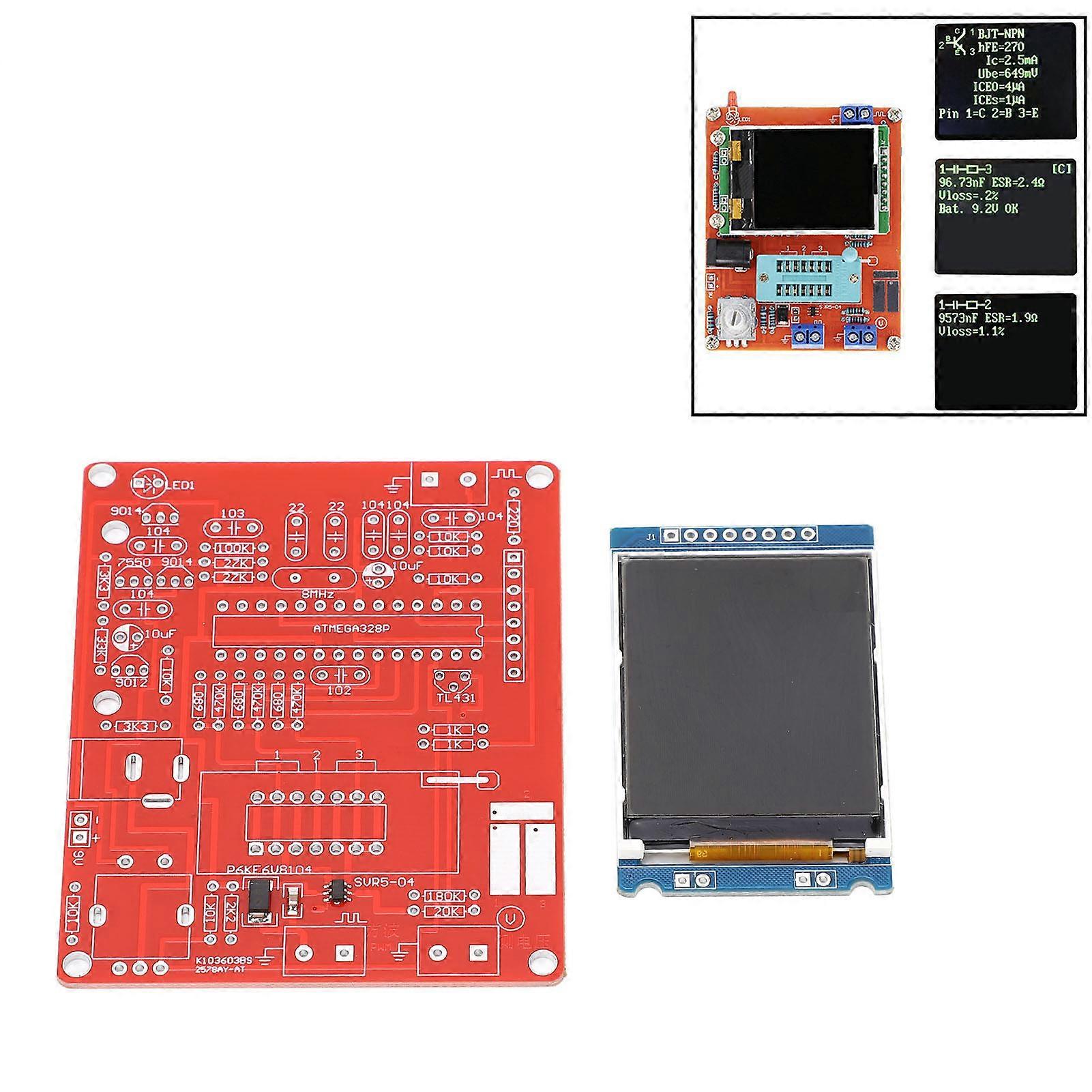
Feature 1Clear Display: The display unit adopts a 160x128 pixel color display screen, with a full screen of 8x20 characters and a color depth of 16 bits. The graphics are displayed as component pattern. 2Smart Testing: Automatically detect NPN and PNP transistors, field effect transistors, diodes, double diodes, thyristors, and thyristors, and automatically determine the outgoing lines of the above transistors. 3Easy Operation: Rotary coding switch control, 1 click measurement, automatic shutdown function. With IC block. And the operation is very easy. 4Power Supply: You can use a 9V stacked battery for power supply or a power adapter for power supply. The current of the entire module is about 30mA, and after shutdown, the current is about 20nA. 5Simple to Install: Comes with a light weight and a compact size as well, the transistor tester is very convenient to install in minutes.Item Type: Transistor TesterDisplay: Using a 160x128 pixel color display screen, with a full screen character count of 8x20, a color depth of 16 bits, and graphic display of component symbols. Switch: Rotary coding switch control, 1 click measurement, automatic shutdown. Battery: 1 x 6F22 DC9V battery powered, shipped without battery. Other Power Supply Methods: power adapter DC 6.8-12V, the overall current is about 30mA, and after shutdown, the current is about 20nA. Test function:1. Automatically detect NPN and PNP transistors, field effect transistors, diodes, double diodes, thyristors, thyristors, and thyristors, and automatically determine the pin distribution of the aforementioned transistors. 2. Test the amplification coefficient of the common emitter current of NPN and PNP transistors, the threshold voltage of the base emitter, and the leakage current of the collector emitter at the cut off time. 3. Identify Darlington triode by emitter threshold voltage and high current amplification coefficient of triode base. 4. Detect the built in protective diodes of power transistors and field effect transistors. 5. Test the gate source conduction threshold voltage, drain source conduction resistance, and gate source capacitance of a field-effect transistor. 6. A maximum of 2 resistors can be measured at a time, so adjustable resistors with three pins can also be measured. If the adjustable resistor is adjusted to the end point, only one resistance value can be measured. 7. The highest resolution for resistance measurement is 0.01 . Can measure up to 50M . 8. The measurement range of the capacitor ranges from 25pF to 100mF, with a resolution of 1pF. 9. For capacitors larger than 90nF, measure their equivalent series resistance ESR at the same time, and the maximum resolution of equivalent series resistance is 0.01 . 10. For capacitors greater than 5000pF, the voltage drop rate after charging is displayed simultaneously, which can reflect the quality factor Q value of the capacitor. 11. Measure up to two diodes at a time and display their positive and negative poles, conduction voltage. 12. Light emitting diodes are also displayed as graphical symbols of diodes, and their conduction voltage is much higher than that of ordinary diodes. 13. A voltage regulator diode with a reverse breakdown voltage below 4.5V can also be detected and displayed as a dual diode pattern. The positive and negative poles are based on the diode patternwith a conduction voltage of around 700mV, while the conduction voltage corresponding to the other diode pattern is the regulated value. So don't measure a regular diode and a voltage regulator diode simultaneously. 14. When testing a single diode, simultaneously test the reverse junction capacitance of its PN junction, and the PN junction capacitance of the transistor can also be tested. At this time, only the base and emitter of the transistor, or the base and collector, can be placed simultaneously. 15. Capacitors below 25pF can also be tested. This test requires preparing a 30pF capacitor, testing the 30pF capacitor first, and then connecting the measured capacitor to it in parallel before measuring again. Subtracting the measured value of the 30pF capacitor from the obtained result. 16. Measure the inductance of resistors below 2100 simultaneously, with a measurement range from 0.01mH to 20H. 17. The testing process takes about 2 seconds, and larger capacitors and inductors will take longer. 18. Additional functions include frequency measurement, voltage measurement, square wave generator, PWM generator, infrared remote control decoding, infrared remote control coding,temperature sensor testing,temperature and humidity sensor testing, color selection, debugging and calibration, continuous testing, and other functions. 19. The frequency measurement range is from 1Hz to 1MHz or higher. When the measured frequency is below 25kHz, the cycle can be displayed, and the resolution can get to 0.001mHz. 20. DC voltage measurement up to 50V. 21. Output one square wave signal, multiple frequency ranges available for se
-
Fruugo ID:
197198933-420505177
-
EAN:
4142380094654